|

Tor Brustad1, Torhild Voss1, Pĺl Kristian Selbo1, Kaare Gärtner1,
Trond Holmřy1, Jahn M. Nesland2, and Kristian Berg1.
1 Department of Biophysics, 2 Department of Experimental Pathology, Institute for Cancer Research, The Norwegian Radium Hospital, Montebello 0310 Oslo, Norway.
![]()
|
![]()
Notes on downloading/viewing video files
Downloading the video sequences may be time consuming. In order to save time it should be noted that the paper may be readable without opening the video sequences 1 and 2. The time for downloading the sequences may also be reduced by downloading several sequences in parallel.
![]()
 |
Video sequence 1 (6.9MB) |
![]()
Abstract
Vital microscopy (VM) deals with microscopic investigations of living cells and tissues. While useful samples of the former usually are easily obtainable from most types of cell cultures, sufficiently thin samples of living tissue are more demanding to attain. A transparent chamber technique is described, by which viable tissue layers of thickness down to 20 mm are generated.
Some examples from the wealth of information inherent in the dynamic scenery associated with the in vivo processes are presented. This is achieved by combination of the video-based vital microscopy technique and the electronic information technology available at the present conference.
The potency of this technology is demonstrated, with examples from studies related to photodynamic therapy (PDT), based on video recordings of chamber tissue as well as of cells from tissue culture.
I) VM-studies of normal chamber tissues to elucidate response patterns of different types of vessels following PDT
The effects were induced by light exposure of the tissue in the transparent chamber at specified times after intra-peritoneal (i.p.) or intra-venous (i.v.) injection of 25 mg kg-1 and 3.1 mg kg-1 body weight (b. w.) of tetra (4-sulfonatophenyl) porphine (TPPS4), respectively tetra (3-hydroxyphenyl) porphine (3-THPP). In both cases photochemical effects were demonstrated;
in venules by showing growth of individual deposits at certain light-exposed sites in the vessel wall, until filling the entire lumen as permanent blood plugs. Alternatively the plugs are shed off and transported in the blood stream as emboli, until trapped when blocking up the blood stream in one arm of nearby vessel bifurcations downstream,
in arterioles by showing a) that myriad's of emboli are formed and shed off in succession from given growth sites, and b) constriction of the vessel, which finally may give rise to permanent or transient interruption of the blood stream.
II) VM-studies of location of photosensitizers in vivo
This effect was demonstrated by fluorescence microscopic analysis of the i.p. injected photosensitizer TPPS2a (disulfonated tetraphenylporphine with the sulfonate groups in adjacent positions) in the viable granular normal tissue of the transparent chamber. In normal tissue, bright fluorescence from the photosensitizer was detected mainly in the microvascular network 24 hrs post administration, while the surrounding tissue was negative. A new method for quantitative analysis of photosensitizer distribution in living tissue was established, based on well founded methods for fluorescence quantification.
III) PDT-effects on cells in tissue culture
Two types of such effects are shown:
a) The dynamics of intracellular release from lysosomes into the cytoplasm of photochemically activated disulfonated aluminium phthalocyanine with 2 sulfonate groups in adjacent positions, AlPcS2a.
This effect was demonstrated by fluorescence video microscopy of NHIK 3025 cells treated with 10 mg/ml AlPcS2a for 18 hrs followed by continuos exposure to the excitation light of the microscope.
b) The dynamics of PDT-induced formation and rupture of blebs on the plasma membrane.
NHIK 3025 cells were treated with 5 mg/ml monosulfonated meso-tetraphenylporphine (TPPS1) for 18 hrs, followed by continuous exposure to the excitation light of the microscope. The treatment induced bleb formation on the plasma membrane, followed by release of the cellular cytoplasm into the extracellular medium. These results indicate that TPPS1 was partly located on the plasma membrane, and that the treatment killed the cells through a necrosis pathway.
![]()
Introduction
Photodynamic therapy (PDT) (or alternatively photochemotherapy (PDT)) is being evaluated world-wide as a method for treatment of light-accessible neoplasms (Dougherty, 1984; Pass, 1993; Amato, 1993) as well as for the treatment of vascular stenosis (Dartsch et al., 1993), bacterial and viral eradication (Malik et al., 1992), psoriasis (Spikes and Jori, 1987), and for the detection of neoplasia (Andersson-Engels et al., 1991). The therapy, as used in cancer treatment, is based on selective uptake and/or retention of a sensitizer in the tumour tissue and cytotoxic effects of the sensitizer in combination with light. For the treatment of patients, lasers are usually used as light sources, because of their high fluence rates and their narrow beams, facilitating application of the light through thin optical fibres (Gomer et al., 1989). The cytotoxic effects are mediated mainly through formation of singlet oxygen (Jori and Spikes, 1984; Moan et al., 1979; Sonoda et al., 1987; Wagner et al., 1987). The advantages of this method as compared to other conventional cancer treatment modalities, are its low mutagenic potential, its low systemic toxicity, and its ability to destroy tumours selectively (Ben-Hur et al., 1987b; Spikes, 1986). Its main limitation is related to the small penetration depth of light into tissue. Tumour tissue further away from the light source (fibre tip etc.) than 1 cm can usually not be inactivated.
The localization of photosensitizers in tumour tissues is dependent upon the molecular structure of the photosensitizer and the way it is administrated, e.g. Photofrin, TPPS4, TPPS3 (meso-tetraphenylporphine with 3 sulfonate groups) and AlPcS4 (aluminium phthalocyanine with 4 sulfonate groups) are mainly located in non-parenchymal areas, whereas TPPS2a, TPPS1, AlPcS2 and AlPcS1 are mainly located in the parenchyme cells (Bugelski et al., 1981; Peng et al., 1991; Kessel et al., 1987). Much work has been performed to elucidate the mechanisms of photochemical cell inactivation and tumour eradication (Henderson and Dougherty, 1992; Moan and Berg, 1992).
The in vivo dynamics of the photochemical process and the mechanisms of tumour eradication have so far mainly been studied indirectly by biochemical and biophysical techniques. Vital microscopy (VM) is an old technique which in its more modern version dates back to pioneering work of Sandison, (1924, 1928), followed up by important, early work of Algire, 1943, Algire and Legallais, 1949, and Woods et al., 1951. Considerable efforts have been placed on up-grading the technique for better to satisfy to-day's requirements to an in vivo model-system for general cancer research, (Endrich and Hammersen, 1986, Falkvoll et al., 1984, Frugĺrd, 1984, Brustad, 1987, Hommersand, 1994).
The main objective of our work was to establish a model which made it possible to observe, record and replay repeatedly dynamic processes related to growth of normal and neoplastic tissue, including perturbed growth caused by use of various growth stimulating and inhibiting drugs, and/or effects of physical agents, like X-rays, light, hyperthermia, etc. Thus, the VM-data presented here are not a result of any systematic study of photodynamic processes and mechanisms. Instead they were among tests in different fields of cancer research, to shed light on the versatility of usefulness of this technique. It is however, our opinion that PDT seems to be a field in which this technique may prove to be particularly useful.
A challenge in vital microscopy is to obtain sufficiently thin and simultaneously functional tissue-layers in living mammals, which repeatedly can be observed and studied microscopically. In the present study video recordings are presented of the photodynamic processes occurring in granular tissues after i.p. treatment with photosensitizing dyes in combination with light.
![]()
Materials and Methods
I) Chemicals
Tetra(3-hydroxyphenyl)porphine (3-THPP), meso-tetraphenylporphine with 1 sulfonate group (TPPS1), meso-tetraphenylporphine with 2 sulfonate groups in adjacent positions (TPPS2a), meso-tetraphenylporphine with 4 sulfonate groups (TPPS4) and disulfonated aluminium phthalocyanine with 2 sulfonate groups in adjacent positions (AlPcS2a), were obtained from Porphyrin Products (Logan, UT).
| Fig. 1: The structural formulas of the five photosensitizers used in the present studies. |
Solutions of 3-THPP and TPPS2a were made by dissolving in a small amount of 0.05 M NaOH, followed by dilution in physiological saline to appropriate concentrations. TPPS4 and AlPcS2a were dissolved in physiological saline.
II) Transparent chambers as an experimental model system
Two chamber techniques have been used in the present study to obtain thin, living tissue-samples. Whereas the ingrowth chamber technique offers a loose connective tissue, sometimes referred to as granulation tissue, the pre-formed tissueslab chamber technique provides a mature connective tissue.
IIA) The ingrowth chamber
IIA1) Design
The design of the ingrowth chamber was based on the rabbit ear chamber, as described by Sudmann, 1975.
 |
| Fig. 2: The ingrowth chamber; to the left in exploded view, to the right in cross section. (For details, see text). |
The chamber (made on licence by A/S Microplast, Stjřrdal, Norway) is
comprised of four parts, with the main unit {A}, moulded in one piece of polycarbonate,
polysterol, or polymethylmethacrylate. Chambers made of polycarbonate do tolerate
short-term sterilization at 121 °C, whereas chambers made of the two other materials were
sterilized by ethyleneoxide autoclaving at 55 °C.
The chamber dimensions, given in mm, are shown in the figure. In the centre of {A} is a tube {A1} with a thin optical top lid {A2}, which is trans-illuminated during microscopy. {A1} is attached to the main chamber house {A5} by 6 spokes {A3}. The main chamber-house is surrounded by a perforated brim {A6}. Inside {A5} is a rim {A4}, located in the same height as that of {A2}. A spacer {B} of appropriate thickness, rests upon this rim. These spacers are stamped out of sheets of appropriate plastic material of pre-selected thickness, by means of a specially made, concentric double-edged hollow punch. When necessary "Kepton" polyimide films, type H are used, manufactured with high precision in sheets of thickness 12.5 mm, 25 mm, 75 mm, and 125 mm by Du Pont Company, USA.
A circular glass cover slip {C} is placed upon the spacer, and the entire assembly is locked together in the main chamber-house by a retaining circlip or fastening ring, {D}. The total weight of the entire chamber assembly is 200 mg.
IIA2) Implantation
| Fig. 3: This figure illustrates schematically the ingrowth chamber implanted in one of the acceptable positions in relation to the various strata of the mouse skin. Wall of main chamber house {1}. Wall of small chamber tube {2}, with its optical end window {4}. Openings between spokes for ingrowth of cells and vessels {3}. Uppermost optical window, (glass) {5}. Granulated tissue fills the space between the optical windows {6}. |
The chamber is implanted in a dorsal skin-fold of mice. As seen from Fig. 3, the openings between the chamber spokes are placed in closest possible contact with an acceptable vasculous strata of the skin, with ingrowth and blood supply initiated from the vascular plexus in reté papillare.
As the first step in the chamber implantation, the anaesthetized mouse is placed on a rubber sheet, and a dorsal skin fold is prepared by stretching out and placing some excess skin as a double-layer between the jaws of a spring clip. This double-layered skin fold is then secured by a couple of through-going stitches, just above the spine.
|
Video sequence 2 (5.9MB) |
Video sequence 2 illustrates the main steps of the chamber insertion:
With a sharp 3 mm hollow punch a hole is made through the skin fold. With a pair of scissors, four radially arranged cuts, each about 2 mm long, are made in one of the skin layers, from the periphery of the hole into the tissue, perpendicular to each other. The stem of a polished steel pin, shaped like an opened umbrella, is then eased through the hole in the skin fold, from the side with the quadrant-marked hole. By use of a small aural wax hook and a pair of tweezers, each of the skin quadrants is carefully and without tearing the tissue, lifted over and placed on the outside of the cone-part of the umbrella. The stem of the steel pin is then secured in vertical position in a hole in a separate steel-foot. With a hollow punch of diameter about 7 mm (see below) a hole is made through that skin layer placed against the surface of the umbrella cone, thus providing a clean-cut enlarged hole from the surface of the skin fold to its middle.
The diameter of the hollow punch must be selected so that the hole in the skin in subsequent operations fits tightly around the chamber wall A5, in Fig. 2. The choice of diameter of the hollow punch to be used is to some extent determined also by the elasticity of the skin of the actual mouse strain used. Following removal of the umbrella shaped steel peg, the chamber is inserted in the pre-formed holes in the skin by sliding the chamber tube (A1 in Fig. 2) into and through the flap, from the side with the enlarged hole. This is done by first pushing a tapered perspex pin into the lumen of A1 until the chamber is secured firmly to the pin. The latter is then used as a guiding "needle" to thread the chamber through the pre-formed holes in the flap. By use of the aural wax hook, the skin around the enlarged hole is lifted carefully and without tearing the tissue, over the perforated brim (A6 in Fig. 2) of the chamber. The skin layer around A1 is finally pressed carefully, but firmly against the spoke level of the chamber. During the entire operation the skin flap is kept moist with physiological saline.
A spacer (B) is now with use of a pair of tweezers, placed on its appropriate position in the chamber, as described in Materials and Methods section IIA1. The chamber is then filled with physiological saline or a growth medium and closed by inserting the circular glass cover slip, which finally is secured by pressing the circlip (fastening ring) carefully against the cover slip.
Although the chamber usually rests quite firmly in the skin fold without any additional measures, a few of the holes in its perforated brim are occasionally used for better to secure the chamber in the skin fold, by a couple of through going stitches.
IIA3) Housing and care of mice carrying ingrowth chambers
From two days prior to chamber insertion and during the entire post insertion period, the mice are kept in a cabinet on a 12-hour light-dark cycle, in which both temperature and relative humidity automatically are stabilised to predetermined settings. HCl was added to the drinking water to a concentration of 1.33 mM, to prevent infection.
The mice are not treated with any antimicrobial agents. To achieve this demanding goal, temperature and humidity settings were established which, although sub-optimal for the growth rate of granulation tissue into the chamber, nevertheless provided acceptable tissue growth in athymic as well as in thymic mice. Under strict hygienic standards in the cabinet, it was found that the stated goal was achieved when temperature and relative humidity were kept at 29 ± 2 °C and 60 ± 7 %, respectively.
After insertion of the chamber, the skin flap is cleaned regularly and carefully, and desquamate epithelium formed around the periphery of the chamber removed whenever necessary. Careful hygienic measures are mandatory, and found to reduce the incidence of local inflammatory reactions originating from the skin enclosing the chamber.
IIA4) The ingrowth process
Following insertion of the chamber in the skin fold, the normal wound-healing mechanism is trigged in such a way that the space between the two windows in the chamber is "considered to be the wound" to be healed. Granulated tissue grows into the chamber from the damaged, vasculous skin layer around A1 (in Fig. 2), through the openings between the spokes, into the chamber, where it gradually fills the space between the windows with living, loose connective tissue and functional microvascular network. The thickness of a completed chamber tissue is given by the distance between the two optical windows (A2 and C in Fig. 2), which equals the thickness of the actual spacer used, (B in Fig. 2).
Under the conditions described, more than 50 % of the chambers inserted in thymic mice were filled completely with granulation tissue. The ingrowth process appears to start about one week after insertion and when successful, the chambers are filled with vasculous loose connective tissue about 2,5 - 3 weeks after insertion of the chambers. In athymic mice on the other hand, ingrowth is more unpredictable. Under our experimental conditions, less than 20 % of the inserted chambers become completely filled with vasculous tissue. In these chambers ingrowth starts about 2 weeks after insertion, and the chambers are filled with functional tissue about 2 weeks later.
Of the remaining 80 % of the chambers, if ingrowth ever starts, it is delayed up to 10 days and ceases at irregular times, with very different degrees of ingrowth, often with only a tiny vasculous segment located in the upper part of the chamber.
With this chamber technique, we have succeed in making tissue layers of thickness down to about 20 mm, which appears to be close to the lower limit for successful ingrowth to occur. Most of our work is performed with tissue of thickness of about 50 mm.
IIA5) Features of the chamber system
Whenever needed the experimenter can uncover temporarily the tissue layer by opening the chamber. Prior to opening, all accessible parts of the chamber and the surrounding tissue are cleaned with an alcohol moistened cotton swab. The circlip is removed by means of a cannula. By pressing the end of a steel rod (diameter = 7 mm) against the chamber window to which a piece of double-sided tape is fastened, the cover slip can with some experience, be lifted off without serious damage to the tissue.
Whenever the chamber is opened, the tissue layer is kept moist with physiological saline to prevent dehydration. The cover slip and sometimes also the spacer, are replaced by new ones when the chamber is opened. Chamber insertion and maintenance are performed in a sterile bench.
With the glass window removed, precision implantation of for instance a tumour spheroid can be made or a drop of a solution can be placed on the exposed tissue by means of a micromanipulator, before the chamber again is closed with a new window. There is also possible to transplant tumour spheroids to the chamber by hand, by use of a Pasteur pipette. This method is of course, not so accurate as the micromanipulator method.
The experiments with the transparent chambers are often carried out in two steps:
First, a series of video recordings are performed to evaluate the dynamics of the effects induced in the living tissue by the photochemical treatment.
Secondly, the chambers are cut out of their skin folds, the tissues fixed while housed in the chambers, then removed under maintenance of their orientation in the chamber. Micro-biopsies can, when found necessary, be taken from these fixed tissue samples at given co-ordinate positions, where video recordings earlier were taken, and prepared for LM, TEM and/or immunohistological analysis, to ease identification of details seen in video recordings.
IIB) The pre-formed tissueslab chamber
IIB1) Design
The design of our pre-formed tissueslab chamber was inspired by that used by Trevan and Young, 1967, in their work with a rat skin flap chamber. The chamber is based on the principle that an appropriate tissue layer in the skin of the experimental animal is uncovered in situ by surgery, and somehow placed between two optical windows, favourable for trans-illumination and microscopic observation/recording.
A short description of our version of a pre-formed tissueslab chamber has previously been presented, (Brustad, 1987).
 |
| Fig. 4: The pre-formed tissueslab chamber in exploded view, used to harbour a mature tissue layer in the dorsal skin fold of mice. (For details, see text). |
Fig. 4 presents a drawing of our chamber to harbour a mature tissue layer in the dorsal skin fold of mice. The chambers are made individually and with high precision in our instrument workshop. As chamber material either polyphenyleneoxide or polysulphone are used. These materials are well suited for processing in the workshop, appear to possess favourable tissue compatible properties and tolerates short term sterilization in standard steam pressure autoclaves at 121 °C.
The chamber consists of two short cylindrical tubes or rings of equal diameter. To one end of each ring a circular optical window is placed into a countersunk groove of depth identical to the thickness of the glass, and fastened by adding a little "Loctite-495" cyanoacrylate adhesive.
A hole can be made through one of the windows prior to insertion (as illustrated in the upper window of Fig. 5). The experimenter can close this hole by placing another circular glass coverslip on top of the former, and fasten it by a lightweight retaining ring or simply by a trace of sticky grease. Thus, this window can be removed temporarily whenever needed. This makes it possible to get access to the chamber tissue at will, during the experiment. (Instead of making a hole through the window, one or more wells (not through-going) can be made in the window, by use of a dental diamond drill set-up. Implants of various types (a tumour seed, a slow-release pellet with for instance a growth-or angiogenesis- factor) can be placed in the wells during insertion of the chamber. Such a window is illustrated in the lower chamber-half in Fig. 5.)
In the outer wall of the upper ring in Fig. 5, some saw-teeth are made with great precision. In the corresponding end of the lower ring, a countersunk groove is made with a precisely determined depth. When the two chamber-ends are led together axially until the tooth points touch the bottom of the countersunk groove, the distance (d) between the two optical windows, and thus the thickness of the tissue layer to be confined between them following implantation, becomes unambiguously determined. We have made a few batches of chambers. All chambers within a given batch are characterized by identical d-values, whereas different batches have different d-values. That batch, which we have used most frequently so far, has a d-value of 200 mm.
A thin, perforated brim surrounds each ring. Some of the holes in the brim are used temporarily for stitches during insertion, others for securing the chamber in the fold following insertion, and two holes are used for light screws to hold the chamber-halves firmly together following insertion. (See Fig. 5, panel A and the following text).
IIB2) Implantation
Implantation of the chamber in the skin fold is performed in a sterile bench, and only a short description of this demanding procedure is given here. For better to understand the principles, reference is made to the drawing presented in Fig. 5.
 |
| Fig. 5: Panel A shows schematically how the inserted chamber is
positioned in relation to major skin plexuses. The pre-formed vascularized tissue layer is
positioned between the windows {2} of the two chamber halves {1}. Two fastening screws are
also seen {3}. See text. Fig. 5: Panel B shows a cross sketch of the skin fold, followed by four illustrations of central steps in the procedure for implantation of the chamber in a dorsal skin fold of mice. |
With a scalpel and a pair of iris scissors a cylindrical tissue slab with diameter equal to that of the chamber, is removed from the surface of the flap down to its mid plane. This is a simple operation, as the mid-plane is easily recognized. Nonvascular pellicles appearing in the bottom of this hole, but belonging to the adjacent layer of the skin fold are removed. The glass-covered end of the upper chamber-half of Fig. 5 is then eased into this pre-formed hole, until the cover glass contacts the tissue in the bottom of the hole. The chamber-half is then secured in this position in the skin fold with a couple of stitches through the chamber brim. The animal is now reoriented so the chamber axis points in vertical direction with the saw-teeth upwards. The skin layer is then pushed towards the latter until the teeth just penetrate the skin layer. This provides an exact definition of the contour of the inserted chamber ring on the outer side of the skin flap. With the iris scissors, a small scalpel, and some high quality tweezers, a demanding surgical removal of the contoured cylindrical tissue slab is then performed under a dissecting microscope, from the surface of the skin flap down towards, but without including or causing serious damage to the deepest lying vascular plexus.
With the aid of a guiding tool (not described here) the glass covered end of the other chamber-half in Fig. 5 is lead axially towards the already inserted chamber-half, until the saw-teeth of the latter touch the bottom of the corresponding countersunk groove of the former, thus confining the intact tissue layer between the two optical windows.
Two lightweight screws through the perforated chamber brim are finally tightened to combine firmly the chamber-halves, and thus secure the proper window separation. (See {3} in Fig. 5, panel A). These latter screws are sometimes replaced by tight sutures.
IIB3) Chamber tissue, housing and care of mice carrying pre-formed tissueslab chambers
Immediately following implantation of this chamber, an inspection in the microscope reveals whether the chamber implantation has been successful. Less than one week after a successful implantation, the chamber is ready for use. Procedures for housing and care of mice carrying this chamber type are identical to those already described for mice with ingrowth chamber.
III) Strains and age of mice
Animals with chamber implanted are always housed in separate cages. Female and male mice are in principle equally useful, but males are more active and cause more pronounced effects of wear and tear on the skin fold. In thin-skinned animals the chambers tend gradually to cut themselves out of the skin fold. In extreme cases this may occur so quickly that ingrowth becomes impossible or ceases before complete ingrowth is achieved.
As the skin becomes thicker and more robust with increasing age of the mice, animals of age less than 3 month are commonly not used. This was found particularly important for hairless and athymic mice. Long lasting experiments with individual animals should, whenever possible, be performed with mice of age 7 months or more, which have proved to carry chambers successfully, occasionally for more than half a year. The athymic mice used earlier were USALB nu/nu, (sometimes called Balb C nu/nu), whereas NCR nu/nu are used at present. The USALB nu/nu-strain was used in the present work. The thymic mice have been C57 Bl or derivatives from that strain.
IV) Microscopes and applied accessories
Video recordings pertaining to the VM-studies of vascular effects, were obtained with use of a Leitz "vital-microscope" and a Leitz Aristoplan microscope. The experimental set-up is basically the same for the two microscopes. Only that pertaining to the Aristoplan microscope is therefore described.
 |
| Fig. 6: The microscope, with various accessories to facilitate vital-microscopic operations. (For details, see text). |
Light from a 12V 50W halogen lamp is led via the condenser through the transparent chamber and interchangeable objectives to a beam splitting system with a multi-viewing attachment {5}, from which certain selected fractions of light is led to a tri-nocular tube {6} for visual inspection of the sample and/or to one of the following three registration units:
a) a JAI 733 SIT low light level, black and white video camera {7},
b) a 3-CCD video camera type JVC, KY-15E {3}, coupled to a S-VHS recorder {17} and corresponding S-VHS monitor {19}, and
c) a 35 mm camera {8} with automatic film advance, coupled to a Wild Photoautomat, MPS 45 {2,9}.
Video recordings pertaining to the VM-studies of vascular effects were carried out in transmission mode with light from the halogen lamp, following passage through a heat filter and a 515 nm long pass filter. Excitation of TPPS4 and 3-THPP was in these studies performed in epi-illumination mode, with light from either a halogen lamp or a 50 W Hg-lamp, following passage through a 390 - 450 nm band pass filter and an adjustable iris aperture. The intensity of the excitation light was adjusted so it did not cause observable effects upon the vasculature in chamber tissue of control mice, following comparable exposure. Furthermore, the vasculature of the mice treated with photosensitizer was found not to be perturbed by exposure to the transmission light. In the following the term "excitation light" will therefore be used to describe light exposures inducing photochemical effects in contrast to the term "transmission light".
The data based on in vivo fluorescence microscopy reported in the present work, was obtained with use of a Carl Zeiss Axioplan microscope, equipped with a CCD-camera (Astromed CCD 3200 Imaging System). The excitation light from a 100 W mercury lamp was filtered through a 395-440 nm band pass filter. A beam splitter at 460 nm and a 610 nm cut off filter at the emission side were used. Pictures of normal or tumour tissue were taken and analysed by use of the Astromed software program.
For the in vitro studies, the cells were exposed to light from a 100 W mercury lamp in a Leitz Ortholux microscope with an epifluorescence set-up. The light was filtered through a 365 nm band pass filter at the excitation side, a 400 nm dicroic beam splitter and a 620 nm long pass filter at the emission side.
To facilitate micromanipulation in/on the uncovered viable tissue in transparent chambers, a micromanipulator assembly {12,14} is fastened to the countersunk slide of the mechanical stage {11}. This coupling is made possible by counterbalancing the weight of the micromanipulator {14} so displacements of the mechanical stage in the vertical direction (z) are not hampered by the weight of the latter. Furthermore, free displacements of the micromanipulator in the horizontal plane (x and y directions) are secured by means of two decks rolling independently on special ball bearings, so-called "Miniature guides" {6,21}.
An advanced micro syringe {13} with interchangeable glass capillary tips, prepared by use of a capillary puller, is mounted on the micromanipulator and equipped with a motor-driven piston inside the cylindrical part of the glass capillary tips, for delivery of pre-programmed aliquots of test -liquids/-suspensions {16}.
V) Experimental procedures
For VM-studies of the dynamics and location of uptake of photosensitizers in vivo/in situ, the concentration of the solutions injected in the mice were adjusted to make the volume of fluid injected less than 0.2 ml. The sensitizers were injected either i.v. or i.p. (see text), for TPPS2a and TPPS4 to a concentration of 25 mg kg-1 body weight (b. w.), and for 3-THPP to a concentration of 3.1 mg kg-1 b. w.
In situ localisation of porphyrins was demonstrated by fluorescence microscopic analysis 24 hrs. post i.p. administration of TPPS2a. Localization of the sensitizer was evaluated in vivo and in situ as described in the previous chapter.
In the in vitro studies of PDT-effects on human cervix carcinoma cells in situ, the line NHIK 3025 was used. The cells were subcultured twice a week in Medium E2a containing 20 % human serum and 10 % horse serum. In some of the experiments the cells were treated with 10 mg/ml AlPcS2a in E2a medium containing 3 % serum (2 % human and 1 % horse) for 18 hrs followed by 1 hr in sensitizer-free medium containing 30 % serum before light exposure. The cells were washed three times with phosphate-buffered saline (PBS), a cover glass gently put on top of the cell layer and excess PBS sucked off the dish. In some experiments the cells were treated with 5 mg/ml TPPS1 for 18 hrs and otherwise treated as described for AlPcS2a, except that the light was filtered through a 390-450 nm band pass excitation filter, a 510 nm dicroic beam splitter and a 620 nm long pass emission filter.
In descriptions of video sequences subjective concepts like "rapid" and "slow" blood flow in different types of vessels are used, without quantification, only based on experience, but from many year's work with transparent chambers.
![]()
Results
|
I) VM-studies of normal chamber tissues to elucidate response patterns of different types of vessels following PDT
Introductory studies have been carried out of how various types of vessels react when subjected to photochemotherapy, following i.p. and i.v. injection of photosensitizers. Disregarding the differences in concentration used for TPPS4 and 3-THPP, for those effects studied here, they appear to be qualitatively similar for the two sensitizers, and independent of the injection route.
D T1: Time interval between injection of photosensitizer and exposure to UV-light and video recording.
IA) PDT-induced effects on the microvasculature, as demonstrated by VM-analysis
The photochemical effect proves among other factors, to depend on both the blood stream velocity and the type of vessel in which the effect is studied.
To shed light on this phenomenon, some of the experiments reported in the following were performed by exciting in epi-illumination mode, only short lengths along individual vessels by use of appropriate band pass filters, while the video recordings of the excited area as well as its surroundings, were performed in transmission mode, with use of appropriate long pass filters. For details see Materials and Methods, section IV.
IA1) VM-analysis of venules with low blood flow
|
Video sequence 3 (6.8MB) |
In this experiment TPPS4 was used, injected i.p., with D T1 = 48 hrs.
In venules with low blood flow it was found that a blood plug gradually was built up, from a local site where the basement membrane presumably is uncovered as a result of retraction of two adjacent endothelial cells. The size of the blood plug increases with increasing exposure time, and finally obstructs completely the blood flow through the vessel. If the light-dose is moderate, the process is reversible, if it is larger - it results in a permanent plug at that particular location.
IA2) Venules with higher blood flow
In this experiment 3-THPP was used, injected i.v., with D T1 = 40 min. In venules with higher blood flow the plug builds up and fills the vessel lumen, but the blood pressure may here be sufficient to loosen the plug and transport it downstream, where it usually enters and obstructs a narrower bifurcation branch.
IA3) Small arterioles with relatively low blood flow
|
Video sequence 5 (6.2MB) |
In this experiment TPPS4 was used, injected i.v., with D T1 = 1 hr. In small arterioles it is often observed that the diameter of the lumen gradually reduces, which upon continued exposure results in a complete constriction. This is obviously a more severe damage, as the tissue-volume downstream which is nourished by an arteriole, can be quite large.
IA4) Larger arterioles with high blood flow
|
Video sequence 6 (4.3MB) |
In this experiment 3-THPP was used, injected i.v., with D T1 = 1 hr. In larger arterioles with high blood flow in "mature" connective tissue (i.e. from a pre-formed tissueslab chamber), the vessel wall is more rigid, and complete constriction was not observed under our experimental conditions. Instead foci are generated, perhaps as proposed for venules above, where platelet plugs are being built up until they fill the lumen. Then they loosen and become pushed downstream, while new ones are built up in the same site. In this way showers of platelet emboli are shed into the blood stream from these generation sites. Up to 20 emboli are recorded arising in succession from one given locus. The consequences of such showers of emboli are likely to be serious, because perfusion and nourishment of still larger local tissue volumes downstream become threatened.
In larger arterioles with high blood flow, constriction of the vessel, as was shown to occur in small arterioles with low blood flow, is not commonly seen. Two major factors may explain this difference. Firstly, the vessel wall of larger arterioles is thicker and physically more robust than that of smaller arterioles. Secondly, the higher intravascular pressure of larger arterioles with high blood flow, counteracts the constriction seen in smaller arterioles with low blood flow.
IB) Vascular and tissue reactions of PDT on chamber tissue, as demonstrated by LM and TEM analyses
Following completion of video recordings, the chamber tissue was treated as described in Materials and Methods, IIA5, and subjected to histological analysis. Below some examples are given of photochemical effects as demonstrated by LM and TEM pictures.
D T2: Time interval between exposure to light and killing of the animal.
After intra-venous injection the porphyrins will first be in contact with the different types of blood cells, lipoproteins, and other serum components. Thus, the concentration of porphyrins in the blood is initially high, for then to decrease as the drug diffuses into the perivascular space.
An early step in the procedures for histological examination of chamber tissue treated with porphyrins, is demonstrated in Fig. 7, taken from the experiment presented in Video sequence 3, with D T2 = 48 hrs.
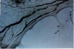
Fig. 7: A tissue removed intact from the chamber, following photochemical treatment in vivo/in situ, is shown floating in a dish with fixative.
This figure shows a 44 mm thick loose connective tissue-sample, photographed under a cover of fixative. Intracapillary inhomogeneities in the distribution of erythrocytes were observed. The light intraluminal spots which are seen, may correspond to blood plugs, which were frequently observed in our vitalmicroscopic recordings.
The following 6 EM-pictures are included as examples of photochemical effects. The pictures refer to chamber tissues as presented and described in Fig. 7. The first three deal with effects on the microvasculature, whereas the three last pictures deal with certain cellular effects in analogous tissue samples.
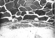
Fig. 8A: This figure which corresponds to Video sequence 6, with D T2 = 2 hrs, shows a capillary crowded with erythrocytes. Two thrombocytes are situated in close contact with the endothelial lining of the capillary. Nuclei of endothelial cells are not seen in this section. The cytoplasmatic processes of endothelial cells seem to constitute parts of a "normal" capillary wall. The piling up of erythrocytes was also recorded in the vitalmicroscopic studies of this and neighbouring vessels, all with unusually low blood flow. The possible adhering of a thrombocyte to the endothelial lining, as indicated in this picture, may be among the first signs of generation of a thrombus.
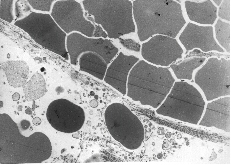
Fig. 8B: This figure refers to an experiment with i.v. injection of 3-THPP at D T1 = 6 days and D T2 = 18 hrs. The capillary shown here lacks totally a normal endothelial lining. All the crowded erythrocytes seem to be held together by an abrupt "lining" of collagen fibres. Some erythrocytes appear nevertheless to have leaked into the structure-less perivascular tissue, which here contains some cell debris. Fibrin-containing structures are seen among the erythrocytes.
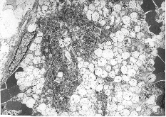
Fig. 8C: This figure which corresponds to Video sequence 3, with D T2 = 48 hrs, demonstrates a thrombus with a massive aggregation - particularly of platelets - and the presence of fibrin, giving rise to the useful, but somewhat imprecise term "platelet plug".
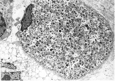
Fig. 8D: This figure is taken from an experiment with i.v. injection of 3-THPP at D T1 = 6 days and D T2 = 18 hrs. A macrophage is shown with its nucleus in a marked peripheral position and its cytoplasm filled up with unidentified material. Part of another cell, seen up to the left, appears to contain the same intracellular substances. Part of a third cell's cytoplasm, seen down to the left, contains empty vacuoles.
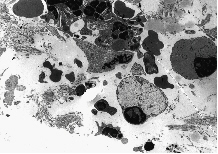
Fig. 8E: This figure refers to an experiment with i.v. injection of 3-THPP at D T1 = 6 days and D T2 = 18 hrs. Lymphocytes are also seen to be influenced by photochemotherapy. Two lymphocytes are located in the right part of the figure, both with pycnotic nuclei strained to the cell membrane. The cytoplasm seems swollen and filled up with structureless material of variable darkness, concealing all traces of normal organelles. Fragments of leucocyte material and collagen debris surround the lymphocytes.
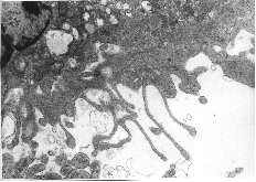
Fig. 8F: This figure corresponds to Video sequence 5, with D T2 = 2 hrs. A great number of the granulocytes in tissue treated with porphyrins and light appear to be highly activated, with swollen knob-like cytoplasmatic extrutions.
II) VM-studies of the dynamics and location of uptake of photosensitizers in vivo/in situ
In situ localisation of porphyrins are demonstrated by fluorescence microscopic analysis 24 hrs. post i.p. administration of 25 mg kg-1 b. w. of the photosensitizer TPPS2a in the viable granular normal tissue of the transparent chamber. In normal tissue, bright fluorescence from the photosensitizer was detected mainly in the microvascular network 24 hrs. post administration, while the surrounding tissue was negative. (See Fig. 9). At this time granular fluorescence could be observed in the endothelial lining of the capillary vessels.
 |
 |
| Fig. 9: Fluorescent (a) and phase contrast (b) vital micrographs of a 44 mm thick normal chamber tissue, 24 hrs. post i.p. administration of 25 mg kg-1 b. w. of TPPS2a. | |
By use of the image-system the fluorescence pattern of the tissue was characterized. The fluorescence distribution of TPPS2a in the normal tissue is presented in Fig. 10.
 |
|
| Fig. 10 : Semi-quantitative fluorescence distribution of normal tissue. Left panel: Fluorescent micrograph of normal tissue 24 hrs. post i.p. administration of 25 mg kg-1 TPPS2a, green box indicating site of measurements. Right panel: Relative amount of fluorescence from indicated box. | |
III) PDT-effects on cells in tissue culture
IIIA) The dynamics of intracellular release of photochemically activated AlPcS2a from lysosomes into the cytoplasm
AlPcS2a has previously been shown to be located in lysosomes and to be relocated into the cytoplasm upon exposure to light (Moan et al., 1994). The dynamics of the release of photochemically activated AlPcS2a are demonstrated by fluorescence video microscopy of NHIK 3025 cells treated with 10 mg/ml AlPcS2a followed by continuos exposure to the excitation light of the microscope.
|
Video sequence 7 (4.3MB) |
In Video sequence 7 the fluorescence from AlPcS2a can initially be seen as granular due to its lysosomal location. After a few seconds of light exposure the fluorescence intensity from the granules, i. e. lysosomes and possibly endosomes, increases and the vesicles can later be seen to burst and the sensitizer released into the cytoplasm. The fluorescence from AlPcS2a in the cells increased several-fold during the light exposure.
IIIB) The dynamics of PDT-induced formation and rupture of blebs on the plasma membrane
NHIK 3025 cells were treated with 5 mg/ml TPPS1 overnight and exposed to the excitation light from the microscope, as described in Materials and Methods section V.
|
Video sequence 8 (2.9MB) |
In video sequence 8 the cells are seen in the transmission (phase contrast) mode. Approximately 5 sec after the initiation of recording of the Video sequence, the fluorescence excitation light was turned on. In the video sequence 40 sec of the treatment, i.e. from 20 sec after initiation of the video sequence, has been omitted. The volume of the cells can clearly be seen to increase during the treatment. During the continuous light exposure, blebs were formed on the plasma membrane, and after 1 min 15 sec (i.e. 35 s in the videosequence) of light exposure, the bleb on the upper left side of the upper cell can be seen to burst and to release its cytoplasm into the extracellular medium. It should also be noted that the cell seems to collapse after the release of cytoplasm (can easily be seen in high speed video mode). Similar results were obtained after treatment of NHIK 3025 cells with 3 mg/ml TPPS2a for 18 hrs followed by exposure to light, as described above (data not shown).
![]()
Discussion
Observation chambers have previously been used successfully to study localization and photochemical effects of photosensitizers in vivo (Star et al., 1986; van Leengoed et al., 1994). Irrespective of whether the microscopic examinations are performed in the epi - or transmission mode, the thickness of the sample to be studied is decisive for the degree of resolution obtained. As shown by Moan et al., 1997, the penetration depth of light, appropriate for excitation of PDT sensitizers like porphyrins, given as the e-1-value, is of the order of some 100 mm. Consequently, even for fluorescence studies of viable tissue, but in particular for VM-work in the transmission mode, it is very important to have access to samples which are as thin as possible.
In animal work two main techniques are in use for obtaining thin, viable tissue samples; the preformed tissueslab technique and the ingrowth technique.
The former is commonly in use to provide samples of thickness from 500 - 300 mm. (Star et al., 1986; van Leengoed et al., 1994). We have developed chambers and microsurgical procedures which allow us to push the thickness of this type of samples downwards towards 200 mm. (See Materials and Methods, section IIB).
The ingrowth type of chambers on the other hand, which is based on the wound healing mechanism, opens for obtaining tissue samples of thickness down towards 1/10th of the minimum thickness of preformed tissueslab chambers. Thus, our technology, as described in Materials and Methods, section IIA, provides viable sample slices of thickness down to about 20 mm. This appears to be close to the lower limit for this type of tissue to be formed, and to remain viable with its imbedded functional microvascular network intact.
The two tissues are however, not identical. It suffices here to say that the former is a mature tissue, whereas the latter is a soft epithelial tissue, i.e. a sort of a granulation tissue, which among other features lack enervated vessel muscles and lymphatic drainage, when used just a few weeks after chamber insertion.
The choice between the two chamber types is therefore not only a question of optical resolution, but also a question of which biological properties the experimenter attaches importance to for his special use of the chamber tissue.
The reduction of thickness of chamber tissue as the ingrowth technique provides, should be expected to improve the optical resolution and thereby the versatility of the technique. In order to understand the mechanisms involved in the cytotoxic effects of PDT, both cells in culture and animal models are used as objects for the treatment. The present introductory study is a first attempt to exploit the improved resolution of the newly developed observation chamber technique to evaluate the effects of PDT down to a single cell level. The results indicate that this technique may be useful even to study effects upon given single cells located in the intact tissue, to shed light on vascular damage (compare Video sequence 6 and Video sequence 3, 4a, 4b, 5) and for in situ localisation of photosensitizers (Fig. 9 and unpublished observations). The mechanisms involved in photochemical treatment can be even further elucidated by combination with established histological techniques (Figs.7, 8a, 8b, 8c, 8d, 8e, 8f). The present study has also shown the benefits of using video technique for presentation of dynamic processes in the scientific literature.
PDT may act through direct effects on the parenchyme cells or indirectly by inducing vascular damage, depending on the type of photosensitizer and the time interval between injection of the photosensitizer and light exposure. The major determinant for vascular photosensitivity appears to be the level of circulating photosensitizer. Thus, shortly after injection, most photosensitizers induce vascular destruction when combined with exposure to light (Henderson and Dougherty, 1992, Video sequences 4a, 4b, 5, 6). When the time between injection of the photosensitizer and light exposure is increased, the importance of vascular damage tends to be reduced, and the direct destruction of the parenchyme cells as well as the non-vascular stroma appears to be of greater importance. However, as found in the present study vascular perturbations, such as destruction of the endothelial lining and lymphocytes, may occur even when the tissue is exposed to light 6 days after injection of 3-THPP (Figs. 8B, D and E).
A variety of effects on the vasculature have previously been described, including blood flow stasis, hemorrhages, vasoconstriction, thrombus formation and blanching of microvessels (Star et al., 1986; Berenbaum et al., 1986; Nelson et al., 1987; Tseng et al., 1988; Zhou, 1989). It was found in the present study, using both hydrophilic (TPPS4) and hydrophobic (3-THPP) tetraphenylporphine, that PDT induces thrombus formation in venules during light exposure (Video sequences 3, 4a, 4b, Fig. 8C). A similar effect was not observed in small arterioles after injection of TPPS4 one hour prior to light exposure, where PDT instead generated vasoconstriction of the vessels (Video sequence 5). This is to some extent in accordance with the results of Berenbaum and coworkers who found that small venules were the most sensitive vessels after treatment with HpD and light (Berenbaum et al., 1986). These authors suggested that such a vessel-dependent differentiation of endothelial sensitivity may be attributed to the numerous histamine H2 receptors in the endothelial lining of venules. This has, however, not yet been documented. Other mediators of thrombus formation, such as von Willebrand’s factor, thromboxane A2, serotonin, tissue factor and loss of acid mucopolysaccharids from the surface of endothelial cells, should also be considered (Foster et al., 1991; Reed et al., 1991; Fingar et al., 1990; Fingar et al., 1991; Contrino et al., 1996; Chaudhuri et al., 1987; Zhou, 1989).
In vessels where the blood flow was sufficiently high, the thrombi formed were frequently seen to be released from the site of origin, and to follow the blood stream until the thrombi were immobilized when reaching vessels with smaller diameter. (Compare Video sequences 3 and 4a, 4b, 6). It is likely that such thrombi or emboli may be released into the circulation causing circulatory obstructions. This is in accordance with the reduction in PDT-induced lethality obtained by combining PDT with anti-inflammatory and anti-coagulatory agents, such as indomethacin, aspirin, warfarin and antihistamine (Ferrario and Gomer, 1990). These agents can inhibit cyclooxygenase activity (indomethacin and aspirin) and thereby reduce prostaglandin and thromboxane synthesis, inhibit synthesis of coagulation factors (warfarin) or inhibit the action of histamine (antihistamine) and reduce blood clotting. Induction of embolism, e.g. pulmonary embolism, and systemic toxicity after PDT, may therefore under given conditions represent a complication of the treatment, although this has so far not been observed in humans.
The thrombi formed during PDT seem frequently to be formed from specific sites on the
endothelial walls. From such sites several consecutive thrombi are formed (Video sequence 6). In all the experiments only a small fraction of the
chamber tissue is exposed to the excitation light. However, the exposed area is always
larger than that in which the thrombi are formed. As an example, in video sequence 6 the
areas subjected to the excitation light were about 5 times larger than the area shown, but
thrombi were nevertheless formed only in the area presented Thus, the thrombi are not
generated randomly, but only at selected sites. (The areas presented in the present
video sequences are smaller than those in the original video recordings. This is done to
reduce the size of the video files.)
It has previously been shown that endothelial cells are more sensitive to PDT than several other cell types (Gomer et al., 1988). PDT has also been shown to damage platelets and to induce release of thromboxane A2 (Henderson and Dougherty, 1992; Reed et al., 1991). The cause of PDT-induced thrombus formation is therefore most likely due to damage of endothelial cells together with activation of platelets followed by adhesion of the platelets to the endothelial lining (Fig. 8A) and thereby inducing thrombus formation. The thrombi contain mainly platelets and less fibrin, probably due to relatively high blood flow through the vessels (Fig. 8C)). (Compared with the blod flow in venules).
Arterioles and arteries are surrounded by smooth muscles which are lacking in venules. In small arterioles with relatively low blood flow, a reduction of the lumen diameter is seen, with complete constriction as the end result of continued light exposure (Video sequence 5). The vasoconstriction of arterioles are most likely due to photochemically induced constriction of the smooth muscles, probably by release of vaso constrictors, and not by stimulation of the sympathetic nerve system in the chamber system. (See above). Thromboxane A2, which is shown to be released after PDT, and serotonin, which may be released during PDT (Fingar et al., 1991), are known to induce vasoconstriction, and may be involved in the PDT-induced vasoconstriction. It is not clear why vasoconstriction is not induced and thrombi are induced in larger arterioles with high blood flow in mature connective tissue (Video sequence 6). However, it should be emphasized that two different photosensitizers were used in these introductory experiments, and further experiments need to be performed to further elucidate this topic.
The vital microscopic techniques as are available in our laboratory, and in particular that based on use of tissue ingrowth, may be useful for detailed evaluation of localization of photosensitizers in situ, due to the reduced thickness of the chamber tissue, (Figs. 9 and 10). Gross evaluation of in situ localization of photosensitizers have been performed by Star and coworkers (van Leengoed et al., 1994) by the use of preformed tissueslab chambers. However, it is to be expected that by reducing the tissue thickness 5-10 fold, the optical resolution should be substantially improved. As shown in the present study, localization of TPPS2a can be studied in detail by the ingrowth chamber system. Twenty-four hours after i.p. injection of TPPS2a the photosensitizer can clearly be seen located mainly in the vasculature. The photosensitizer is found to a higher extent at the rim of the vessels, indicating an endothelial localization. The granular fluorescence observed in the same area may be due to localization of TPPS2a in endosomes and lysosomes, as previously described (Berg et al., 1990).
Vital microscopy combined with video recording has in the present study proved to be a highly useful tool for evaluation and documentation of dynamic processes both in tissue in vivo/in situ (Video sequences 3, 4a, 4b, 5, 6) as well as in cells in culture (Video sequences 7 and 8). Lysosomally located photosensitizers have previously been shown to relocate after exposure to light (Berg et al., 1991). In the present study the dynamics of this process has for the first time been documented. Studies of relocation of photosensitizers during continous illumination from the excitation light of the microscope are influenced by the photobleaching rate and the intracellular concentration of the photosensitizer. Phthalocyanines have in general a low rate constant for photobleaching. Thus, the fluorescence from AlPcS2a can be seen to be relocated and to increase during light exposure (Video sequence 7). The increase in fluorescence is most likely due to monomerization of the photosensitizer, as previously described (Berg et al., 1989; Moan et al., 1994). Many other photosensitizes will be photobleached completely before relocation can be observed under conditions commonly used for cell studies. However, this may be compensated for by increasing the intracellular concentration of the photosensitizer. This has been observed with some sulfonated tetraphenylporphines (unpublished observations).
By use of Coulter counters cells has previously been shown indirectly to increase in volume after photochemical treatment (Moan et al., 1982). As seen in the present study, the cell volume increases also in cells still attached to the substratum (Video sequence 8). PDT induces blebs on the plasma membrane, which are sites for membrane rupture upon further illumination. Due to video recordings the cytoplasm can be seen to be released from one of the blebs formed. Similar observations have been experienced using Photofrin as a sensitizer (unpublished observations). The increased cell volume is most likely due to plasma membrane damage leading to a high intracellular osmotic pressure. The bleb formation may be due to rupture of the binding between the cellular cytoskeleton and the cell membrane, leading to hyperfragile sites on the plasma membrane. Kessel has suggested that photochemical damage to the plasma membrane may cause necrotic cell death to a higher extent than when intracellular organelles are targeted (Kessel, 1997). The present study clearly shows that the plasma membrane can be damaged with necrosis induced immediately and during light exposure (Video sequence 8).
Photofrin is today the predominant photosensitizer in clinical PDT. It has several well-known limitations, and a large number of new photosensitizers have been developed from which a few is presently under clinical investigations. In order to select the optimal photosensitizer for each type of malignancy to be treated and to work out the optimal treatment conditions, the mechanisms and efficacy of tumor eradication should be further elucidated. It is for example still not clear whether the vasculature or the parenchyme cells in the tumor should be preferentially targeted, and to what extent vascular and non-vascular damage are important factors in tumor eradication under different treatment conditions. The present study indicates that vital microscopy using the presented chamber techniques, may be potentially very useful in studying mechanisms involved in photobiological processes on living tissues during and after photochemical treatment. The techniques can also be used to study treatment of tumors without losing much optical resolution (unpublished observations). By performing careful dosimetry of the excitation light used for exposure of the biological specimens, the developed techniques may even be useful for studies of mechanisms involved in given treatment situations.
![]()
Acknowledgements
This work was financially supported by the Norwegian Cancer Society. We are deeply indebted to the veterinarian Lena Kjempengren, and her enthusiastic technicians, Karin Stensland, Tone Ekstrřm, and Hanne Gisholt for their skilful and conscientious work with the mice.
We are also grateful to the technical staff of the Department of Pathology, Inga Finseth, Elisabet E. Mřlsted, Ellen Hellesylt, and Inger Liv Nordli for their invaluable work with the histological samples. Bjřrn Hřvik and Siv Kjřlsrud at the Department of Biophysics, are acknowledged for preparation of figures.
We also would like to express our gratefulness to professor Erik O. Pettersen and Charlotte Borka for their expert help with cells in tissue culture.
![]()
Text for oral presentation of content of video sequences
A) Video sequence 1
This is the vital microscopy set-up. A transparent chamber is inserted in a dorsal skin fold of mice. Wound healing processes are trigged and fill the chamber with granulation tissue.The viable tissue in the chamber is recorded with a microscope equipped with a video camera. The signals from the camera are led via a recorder to the monitor, where the chamber tissue with its functional properties, like blood flow, is displayed.
B) Video sequence 2
This video sequence shows how the transparent chamber is inserted in the skin fold. First some of the skin is pulled up as a double-layer on the dorsal side of the mouse. A 3 mm hole is made right through the fold. This hole is enlarged a little on one side of the fold, from the surface to its centre. The transparent chamber, weighing only 200 mg, has the same cross section as that of this pre-formed hole. The chamber is now placed in the hole, just like a button in a buttonhole.
C) Video sequence 3
Here a functional venule with moderate blood flow is seen. The mouse is treated with appropriate photosensitizer, and the excitation light is adjusted with an aperture so it exposes only an area just a little larger than that presented on the screen. In the lower part of the screen some deposit is seen to adhere to the inner surface of the vessel. The deposit grows larger and larger, until it appears to fill the entire vessel lumen. Initially, the deposit is seen to be leaky, just like a strainer, but gradually more and more of its pore holes become clogged up, and a blood plug is the end result.
D) Video sequence 4a
Here a venule is shown with a blood flow a little higher than that presented in the previous video sequence. A blood plug is seen to be built up in the vessel, here in the upper part of the screen. More and more of its pore holes become gradually filled. Some of the blood is now forced into other vessels, often even by reverting their earlier flow direction. Just in front of the blood plug, an example is seen of a capillary tributary which is in the process of taking over some of the blood flow from the obstructed major venule.
D) Video sequence 4b
This is a continuation of the previous video sequence. The vessel structure below the blood plug - presented in the previous sequence - will first be inspected:
Here the former plug is seen again. Below the plug some contributory venules are seen to help to maintain some flow in the vessel. Further down along the major venule, the first bifurcation below the plug is seen.
The video sequence returns now to - and focuses again on the original plug. Because of the high pressure, the plug is now seen to loosen and to be pushed downstream in the blood flow - until the embolus reaches the first bifurcation downstream, where it becomes trapped and thereby blocks one of these vessel arms.
E) Video sequence 5
Here a small arteriole with relatively low blood flow is presented. As in previous sequences, the appropriate sensitizer is injected in the mouse, and excitation light is limited to just an area a little larger than that presented on the monitor screen. The observer is asked to focus primarily on the diameter of this vessel:
In contrast to what earlier has been shown, after some light exposure, the diameter of the arteriole is seen to decrease, initially slowly, but then with increasing rate, until it is too small for any blood cell to pass through, even for erythrocytes and platelets.
F) Video sequence 6
Here a larger arteriole is seen in a 200 mm thick pre-formed tissueslab chamber. Because the resolution here is poor, the arteriole is seen only as a diffuse, red structure across the screen. In the centre of the screen a blood plug is being formed in the vessel. It grows gradually larger, but is seen to be shed off into the rapid blood flow. Another blood plug is however, being formed in just the same location in the vessel, but also this plug is shed off. Some similar examples are also presented. In the original video sequence, from which this presentation was taken, more than 20 plugs were recorded to be shed off into the blood stream from this particular vessel site.
G) Video sequence 7
Here 5 cells are initially seen in transmission light modus which are from 00:03 continously exposed to UVA light. The NHIK 3025 cells were treated with AlPcS2a prior to light exposure (see Materials and Methods, section V). The granular fluorescence from the photosensitizer, due to its lysosomal and endosomal localisation, can be seen. The localisation and intensity of the fluorescence emitted are apparently unaffected by the light exposure, until about 27:00. The fluorescence from AlPcS2a can upon further illumination be seen to increase in intensity and to be redistributed and to cover nearly the whole extranuclear cytoplasm. AlPcS2a does not seem to be photobleached during exposure to the excitation light.
H) Video sequence 8
The cells are here continously exposed to transmission light and from 00:05 also exposed to the excitation light from the mercury lamp. The cells were prior to light exposure treated with TPPS1 as described in Materials and Methods (section V). By removing 20 sec of the original video strip from 20:00, an increase in cellular volume can clearly be seen. At the left side of the upper cell, the plasma membrane can be seen to rupture at 35:00 and to release parts of its cytoplasm into the extracellular medium. At the same time the whole cell can be seen to collapse, especially by studying the right side of the same cell.
![]()
References
Algire, G.H. (1943). An adaption of transparent chamber-technique to the mouse. J. Natl. Cancer Inst. 4, 1-11.
Algire, G.H. and Legallais, F.Y. (1949). Recent developments in transparent-chamber technique as adapted to the mouse. J. Natl. Cancer Inst. 10, 224-253.
Amato, I. (1993). Cancer therapy. Hope for a magic bullet that moves at the speed of light. Science 262, 32-33.
Andersson Engels, S., Johansson, J., Svanberg, K., and Svanberg, S. (1991). Fluorescence imaging and point measurements of tissue: applications to the demarcation of malignant tumors and atherosclerotic lesions from normal tissue. Photochem. Photobiol. 53, 807-814.
Ben-Hur, E., Fujihara, T., Suzuki, F., and Elkind, M.M. (1987). Genetic toxicology of the photosensitization of Chinese hamster cells by phthalocyanines. Photochem. Photobiol. 45, 227-230.
Berenbaum, M.C., Hall, G.W., and Hoyes, A.D. (1986). Cerebral photosensitisation by haematoporphyrin derivative. Evidence for an endothelial site of action. Br. J. Cancer 53, 81-89.
Berg, K., Bommer, J.C., and Moan, J. (1989). Evaluation of sulfonated aluminum phthalocyanines for use in photochemotherapy. A study on the relative efficiencies of photoinactivation. Photochem. Photobiol. 49, 587-594.
Berg, K., Madslien, K., Bommer, J.C., Oftebro, R., Winkelman, J.W., and Moan, J. (1991). Light induced relocalization of sulfonated meso-tetraphenylporphines in NHIK 3025 cells and effects of dose fractionation. Photochem. Photobiol. 53, 203-210.
Berg, K., Western, A., Bommer, J.C., and Moan, J. (1990). Intracellular localization of sulfonated meso-tetraphenylporphines in a human carcinoma cell line. Photochem. Photobiol. 52, 481-487.
Brasseur, N., Ali, H., Langlois, R., Wagner, J.R., Rousseau, J., and van Lier, J.E. (1987). Biological activities of phthalocyanines--V. Photodynamic therapy of EMT-6 mammary tumors in mice with sulfonated phthalocyanines. Photochem. Photobiol. 45, 581-586.
Brustad, T. (1987). Intravital microscopy in the study of tumor growth. In: Proceedings of the Nordic Meeting on Medical and Biological Engineering, Trondheim, Norway. June 28 - July 1. 33-38.
Bugelski, P.J., Porter, C.W., and Dougherty, T.J. (1981). Autoradiographic distribution of hematoporphyrin derivative in normal and tumor tissue of the mouse. Cancer Res. 41, Pt 1:4606-12.
Chaudhuri, K., Keck, R.W., and Selman, S.H. (1987). Morphological changes of tumor microvasculature following hematoporphyrin derivative sensitized photodynamic therapy. Photochem. Photobiol. 46, 823-827.
Contrino, J., Hair, G., Kreutzer, D.L., and Rickles, F.R. (1996). In situ detection of tissue factor in vascular endothelial cells: correlation with the malignant phenotype of human breast disease. Nat. Med. 2, 209-215.
Dartsch, P.C., Coppenrath, E., Coppenrath, K., and Ischinger, T. (1993). Photodynamic therapy of vascular stenosis: results from cell culture studies on human endothelial cells. Coron. Artery Dis. 4, 207-213.
Dougherty, T.J. (1984). Photodynamic therapy (PDT) of malignant tumors. Crit. Rev. Oncol. Hematol. 2, 83-116.
Endrich, B. and Hammersen, F. (1986). Morphologic and hemodynamic alterations in capillaries during hyperthermia. In: Hyperthermia in Cancer Research. L.J. Angghileri and J. Robert, eds. (Boca Raton, Florida: CRE-press, Inc.). 17-49.
Falkvoll, K.H., Rofstad, E.K., Brustad, T., and Marton, P. (1984). A transparent chamber for the dorsal skin fold of athymic mice. Exp. Cell. Biol. 52, 260-268.
Ferrario, A. and Gomer, C.J. (1990). Systemic toxicity in mice induced by localized porphyrin photodynamic therapy. Cancer Res. 50, 539-543.
Fingar, V.H., Wieman, T.J., and Doak, K.W. (1990). Role of thromboxane and prostacyclin release on photodynamic therapy-induced tumor destruction. Cancer Res. 50, 2599-2603.
Fingar, V.H., Wieman, T.J., and Doak, K.W. (1991). Changes in tumor interstitial pressure induced by photodynamic therapy. Photochem. Photobiol. 53, 763-768.
Foster, T.H., Primavera, M.C., Marder, V.J., Hilf, R., and Sporn, L.A. (1991). Photosensitized release of von Willebrand factor from cultured human endothelial cells. Cancer Res. 51, 3261-3266.
Frugĺrd, L.H. (1984). Vital-microscopy of tissue in transparent chamber in athymic mice. Master of Science degree. The Norwegian University of Technology, NTNU.1-91.
Gomer, C.J., Rucker, N., and Murphree, A.L. (1988). Differential cell photosensitivity following porphyrin photodynamic therapy. Cancer Res. 48, 4539-4542.
Gomer, C.J., Rucker, N., Ferrario, A., and Wong, S. (1989). Properties and applications of photodynamic therapy. Radiat. Res. 120, 1-18.
Henderson, B.W. and Dougherty, T.J. (1992). How does photodynamic therapy work? Photochem. Photobiol. 55, 145-157.
Hommersand, J.M. (1994). Vital-microscopy studies of transparent chamber tissue. Master of Science degree. University of Oslo. 1-80.
Jori, G. and Spikes, J.D. (1984). Photobiochemistry of porphyrins. In Topics in Photomedicine. K.C. Smith, ed. (New York: Plenum Press), pp. 183-318.
Kessel, D., Thompson, P., Saatio, K., and Nantwi, K.D. (1987). Tumor localization and photosensitization by sulfonated derivatives of tetraphenylporphine. Photochem. Photobiol. 45, 787-790.
Kessel, D., Luo, Y., Deng, Y.Q., and Chang, C.K. (1997). The role of subcellular localization in initiation of apoptosis by photodynamic therapy. Photochem. Photobiol. 65, 422-426.
Malik, Z., Ladan, H., and Nitzan, Y. (1992). Photodynamic inactivation of Gram-negative bacteria: problems and possible solutions. J. Photochem. Photobiol. B 14, 262-266.
Moan, J., Pettersen, E.O., and Christensen, T. (1979). The mechanism of photodynamic inactivation of human cells in vitro in the presence of haematoporphyrin. Br. J. Cancer 39, 398-407.
Moan, J. and Berg, K. (1992). Photochemotherapy of cancer: experimental research. Photochem. Photobiol. 55, 931-948.
Moan, J., Berg, K., Anholt, H., and Madslien, K. (1994). Sulfonated aluminium phthalocyanines as sensitizers for photochemotherapy. Effects of small light doses on localization, dye fluorescence and photosensitivity in V79 cells. Int. J. Cancer 58, 865-870.
Moan, J., Berg, K., and Iani, V. (1997). Action spectra of dyes relevant for photodynamic therapy. In: Quantitative Dat. In Quantitative Data of 2nd and 3rd Generation Photosensitizers for PDT. A laboratory manual. J.G. Moser, ed., London: Harwood Publishers, in press.
Moan, J., Johannessen, J.V., Christensen, T., Espevik, T., and McGhie, J.B. (1982). Porphyrin-sensitized photoinactivation of human cells in vitro. Am. J. Pathol. 109, 184-192.
Nelson, J.S., Liaw, L.H., and Berns, M.W. (1987). Tumor destruction in photodynamic therapy. Photochem. Photobiol. 46, 829-835.
Pass, H.I. (1993). Photodynamic therapy in oncology: mechanisms and clinical use. J Natl. Cancer Inst. 85, 443-456.
Peng, Q., Moan, J., Farrants, G., Danielsen, H.E., and Rimington, C. (1991). Localization of potent photosensitizers in human tumor LOX by means of laser scanning microscopy. Cancer Lett. 58, 17-27.
Reed, M.W., Schuschke, D.A., and Miller, F.N. (1991). Prostanoid antagonists inhibit the response of the microcirculation to "early" photodynamic therapy. Radiat. Res. 127, 292-296.
Sandison, J.C. (1924). A new method for microscopic study of living growing tissue by the introduction of a transparent chamber in the rabbits ear. Anat. Rec. 28, 281-287.
Sandison, J.C. (1928). The transparent chamber of the rabbit`s ears giving a complete description of improved techniques of construction and introduction and general account of growth and behavior of living cells and tissues as seen with the microscope. Am. J. Anat. 41, 447-472.
Star, W.M., Marijnissen, H.P., van den Berg-Blok, A.E., Versteeg, J.A., Franken, K.A., and Reinhold, H.S. (1986). Destruction of rat mammary tumor and normal tissue microcirculation by hematoporphyrin derivative photoradiation observed in vivo in sandwich observation chambers. Cancer Res. 46, 2532-2540.
Sonoda, M., Krishna, C.M., and Riesz, P. (1987). The role of singlet oxygen in the photohemolysis of red blood cells sensitized by phthalocyanine sulfonates. Photochem. Photobiol. 46, 625-631.
Spikes, J.D. (1986). Phthalocyanines as photosensitizers in biological systems and for the photodynamic therapy of tumors. Photochem. Photobiol. 43, 691-699.
Spikes, J.D. and Jori, G. (1987). Photodynamic therapy of tumours and other diseases using porphyrins. Lasers in Medical Sciences 2, 2-15.
Sudmann, E. (1975). Vital microscopy of bone remodeling in rabbit ear chambers. Acta. Orthop. Scand. Suppl. 160, 3-115.
Trevan, D. and Young, S. (1967). Eight millimeter cinemicroscopy of transparent chamber in the skin of the rat. In: In vivo techniques in histology. G.H. Bourne, ed. Baltimore, William & Wilkins. 181-191.
Tseng, M.T., Reed, M.W., Ackermann, D.M., Schuschke, D.A., Wieman, T.J., and Miller, F.N. (1988). Photodynamic therapy induced ultrastructural alterations in microvasculature of the rat cremaster muscle. Photochem. Photobiol. 48, 675-681.
van Leengoed, H.L., Cuomo, V., Versteeg, A.A., van der Veen, N., Jori, G., and Star, W.M. (1994). In vivo fluorescence and photodynamic activity of zinc phthalocyanine administered in liposomes. Br. J. Cancer 69, 840-845.
Wagner, J.R., Ali, H., Langlois, R., Brasseur, N., and van, L.J.E. (1987). Biological activities of phthalocyanines--VI. Photooxidation of L-tryptophan by selectively sulfonated gallium phthalocyanines: singlet oxygen yields and effect of aggregation. Photochem. Photobiol. 45, 587-594.
Woods, W.B., Smith, M.R., Perry, W.D., and Berry, J.W. (1951). Studies on the cellular immunology of acute bacteriemia, I: Intravascular leucocyte rection and surface phagocytosis. J. Exp. Med. 94, 521-548.
Zhou, C.N. (1989). Mechanisms of tumor necrosis induced by photodynamic therapy. J. Photochem. Photobiol. B 3, 299-318.